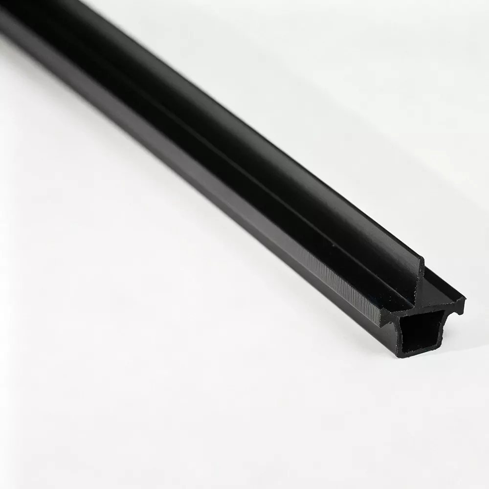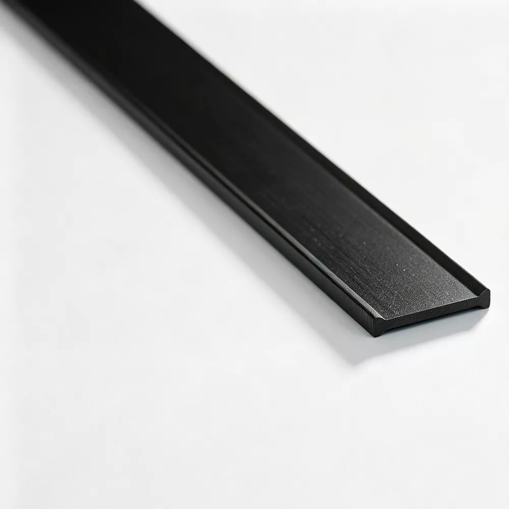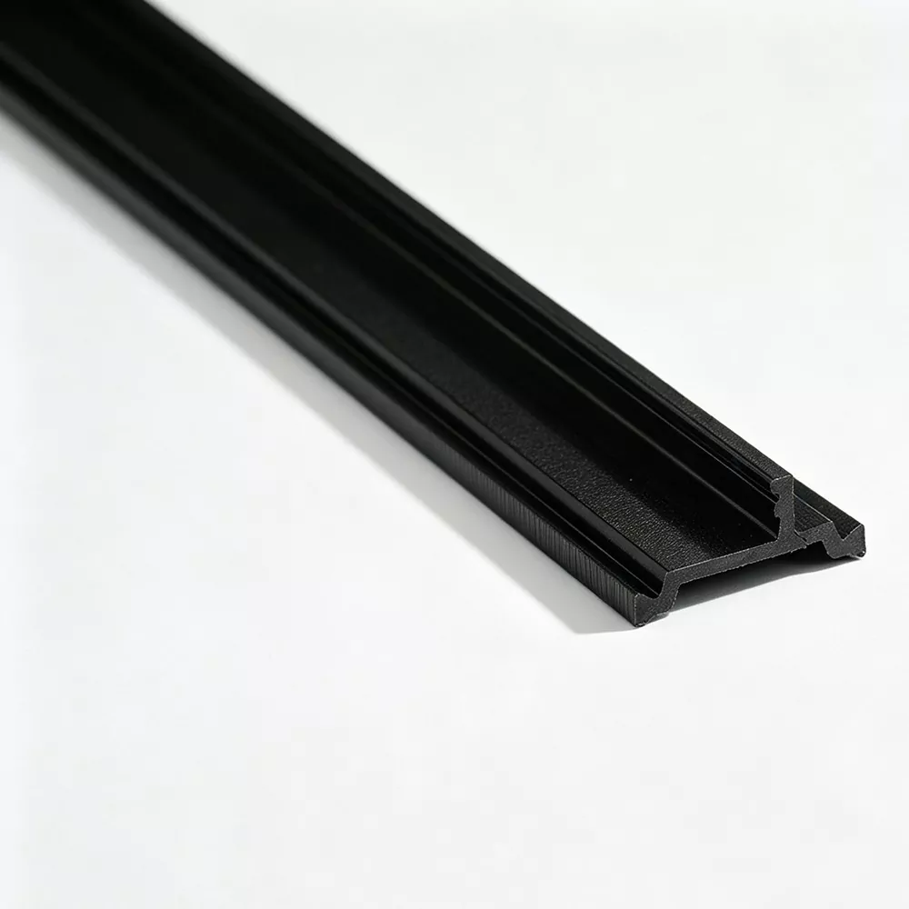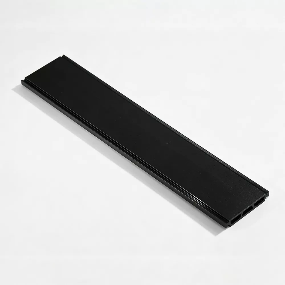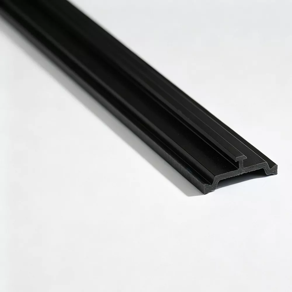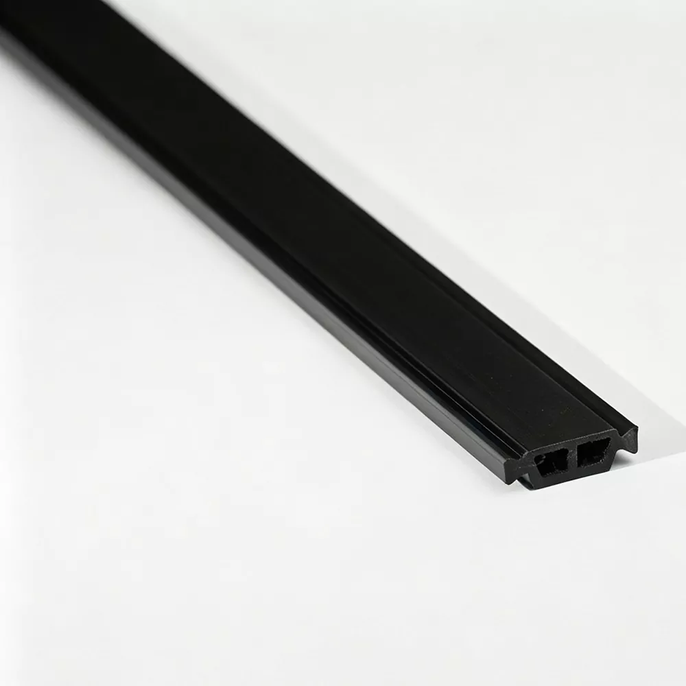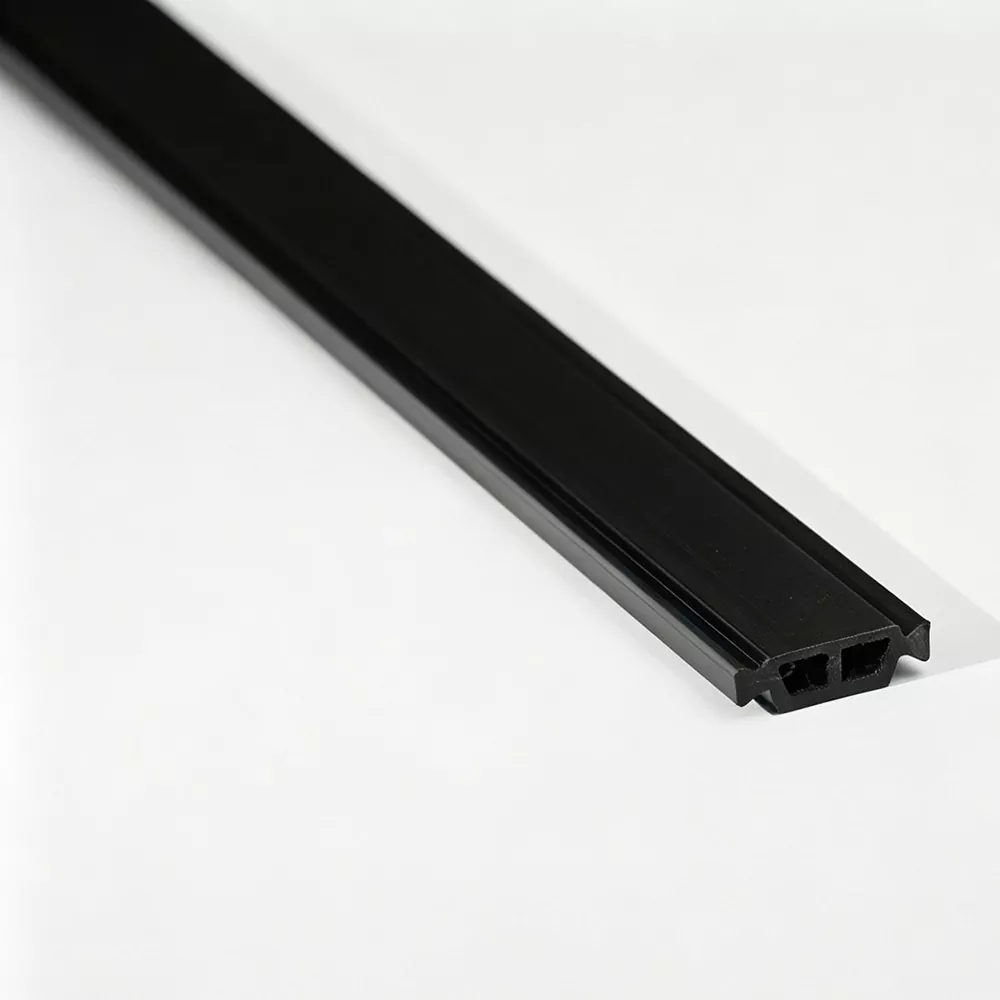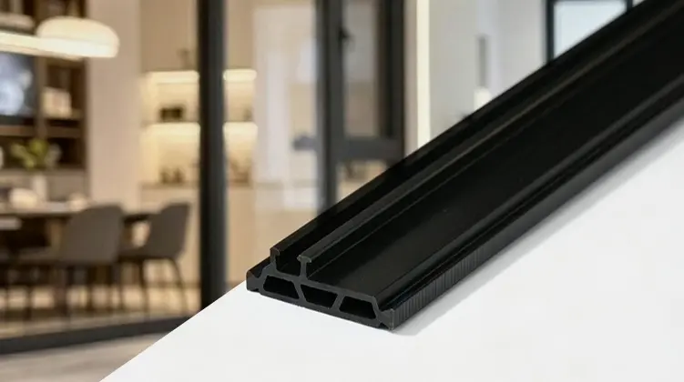
Thermal Break Strips for thermally broken aluminum systems depend on more than a low-conductivity component. The insulation profile must fit the aluminum cavity accurately, stay mechanically engaged during assembly, and remain dimensionally stable through service. This guide explains how PA66 GF25 profiles work, how the aluminum extrusion determines the section, how production conditions affect consistency, and which technical details should be reviewed before a specification is finalized.
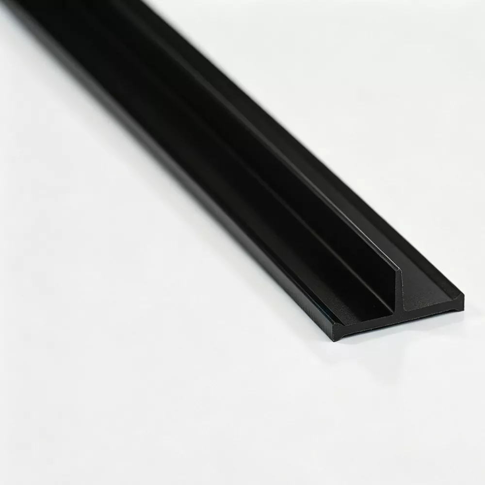
For a thermally broken aluminum frame, the insulating section sits between separated aluminum members and interrupts the direct metallic heat-transfer route. PA66 GF25 is suitable for this role because the nylon matrix provides a non-metallic barrier while 25% glass-fiber reinforcement adds the rigidity and dimensional stability required for profile assembly. Performance, however, is not determined by material alone. Cavity width, cavity depth, groove geometry, locking shape, required separation, strip thickness, and the insertion or rolling method all influence section selection. A reliable specification therefore starts with the actual aluminum extrusion and follows the component through extrusion, cooling, shaping, cutting, inspection and final assembly considerations.
Click a section below to jump directly to the topic you need.
Aluminum is useful in windows, doors and façade framing because it combines structural strength with a relatively low-maintenance surface. Its high thermal conductivity also creates a challenge: when interior and exterior aluminum members remain directly connected by metal, heat can travel through the frame along a continuous conductive path. A thermally broken design changes that path by placing a non-metallic section between the separated aluminum components.
The purpose of Thermal Break Strips is therefore not simply to “fill a gap.” The inserted profile has to maintain a controlled separation while also functioning as a structural interface. It must remain seated inside the aluminum cavity, resist movement caused by assembly forces, and preserve the geometry required by the finished frame. The thermal function and the mechanical function are linked.
Core principle: the aluminum extrusion provides the frame structure, while the polyamide section interrupts the direct metallic bridge between the interior and exterior portions. The final result depends on both thermal separation and secure engagement.
Heat does not move through a frame in only one direction. It follows the available conductive routes through the materials and joints. A continuous aluminum path can therefore bypass the intended insulated cavity unless the system is designed to interrupt that route. A correctly located polyamide section reduces the direct metal-to-metal connection and creates a longer, less conductive path through the assembly.
This is why geometry matters as much as the nominal material description. Two profiles made from the same reinforced polymer can behave differently when their widths, heights, locking shapes or wall thicknesses do not match the intended extrusion.
In practical production, the component must also survive the actions applied during insertion and roll forming. A profile that insulates well but cracks during assembly, slips in the cavity or lacks sufficient shear resistance cannot provide a dependable production solution. The engineering objective is to achieve thermal interruption without sacrificing assembly stability.
For this reason, section selection should begin with the aluminum profile rather than with a generic product label. The shape is part of the engineering specification.
Polyamide 66 reinforced with 25% glass fiber, commonly identified as PA66 GF25, is suitable for thermally separated aluminum profile systems because it combines a non-metallic structure with the rigidity needed at the assembly interface. The glass fibers reinforce the polymer matrix and help the profile maintain its shape under mechanical loading.
For architectural profile production, that combination has a practical advantage: the insulating section is not expected to act as a loose insert. It is formed into a precise section that must stay engaged with the aluminum while the assembled frame is handled, fabricated and used.
The reinforced matrix improves rigidity and mechanical stability, helping the section withstand insertion, rolling and continued engagement within the aluminum profile.
Accurate dimensions help the profile remain properly fitted to the cavity, which is essential when the aluminum groove has a defined locking geometry.
The polyamide segment interrupts the direct metal heat-transfer route between separated interior and exterior aluminum sections.
Controlled extrusion, cooling and shaping conditions support consistency across the length of the finished profile.
A higher-strength material does not automatically solve an incorrect cross-section. If a locking feature is too large, the insertion force may become excessive. If the engagement area is too small, the profile may not achieve the required mechanical hold. If the wall thickness is unsuitable, localized stress can concentrate during assembly.
PA66 GF25 should therefore be considered as one part of the design system. Material selection, extrusion quality and section geometry need to work together.
Nylon materials are sensitive to moisture during processing. Incoming material control and disciplined extrusion conditions help reduce variability in melt behavior and finished dimensions. For this reason, checking material moisture, melt flow characteristics and glass-fiber content is useful before production begins.
The same principle applies to cooling and shaping. A profile leaving the die is not yet a finished, dimensionally stable component. The downstream process influences how the section settles into its final shape and therefore how consistently it fits the aluminum cavity.
Practical takeaway: PA66 GF25 provides the material foundation for a strong thermally separated interface, but the finished profile still depends on extrusion control, cooling, shaping, dimensional inspection and compatibility with the aluminum extrusion.
There is no universal strip section that fits every aluminum extrusion. The cavity created by the aluminum profile defines the physical space available for the insulating component, while the locking structure determines how the component is held. A technically sound selection process therefore starts by studying the extrusion rather than choosing a section from a name alone.
When a new thermally broken system is developed, the required dimensions should be considered together. A change in cavity depth can affect profile height. A change in groove shape can affect the locking geometry. A change in the required separation can affect the available wall thickness. These dimensions form a connected design problem.
| Aluminum Profile Factor | Related Insulation Requirement | Why It Matters |
|---|---|---|
| Cavity width | Profile width | The section must occupy the cavity without excessive looseness or insertion force. |
| Cavity depth | Profile height | Height influences how the component sits inside the aluminum and how much engagement is available. |
| Groove structure | Locking geometry | Matching the groove is essential for stable mechanical retention. |
| Required separation | Wall thickness and section shape | The profile must create the intended non-metallic separation without interfering with assembly. |
| Assembly process | Insertion and rolling compatibility | The section must tolerate the forces and movement associated with the chosen production method. |
An aluminum profile drawing can reveal the cavity dimensions, groove configuration, section tolerances and surrounding wall geometry that a product name cannot communicate. When the section is unusual, the drawing also reduces the risk of selecting an apparently similar profile that has a different locking structure.
Important information includes the cavity width and depth, the groove shape, the intended orientation, required separation, and any dimensional constraints imposed by the final frame. Assembly requirements should be recorded at the same time.
Common I-Type, C-Type and T-Type sections cover many established aluminum profile structures. Their usefulness comes from recognizable cross-sectional patterns, not from a claim that one shape is suitable for all systems. Special-shaped sections are relevant when the aluminum extrusion uses a distinct cavity or locking arrangement.
A customized section can be developed around the actual extrusion geometry. The objective is not to create complexity for its own sake, but to make the polymer profile work with the mechanical interface already defined by the aluminum design.
Jinxing can review a profile drawing before production to determine whether an existing section is appropriate or whether a special cross-section is required.
The cross-section controls how the polymer component interacts with the aluminum. Small dimensional changes can alter insertion force, locking behavior and load distribution. In a production environment, these differences become visible when operators encounter difficult insertion, localized cracking, incomplete engagement or inconsistent roll forming.
During insertion, the profile has to enter the aluminum cavity with a controlled level of resistance. Too little resistance can indicate insufficient engagement and may make the profile more vulnerable to movement. Too much resistance can increase assembly force and place unnecessary stress on the section or surrounding aluminum features.
Dimensional consistency along the extrusion is therefore important. A section that is accurate at one point but varies noticeably elsewhere can produce an uneven assembly experience. Controlled pulling speed, cooling conditions and shaping help reduce this type of variation.
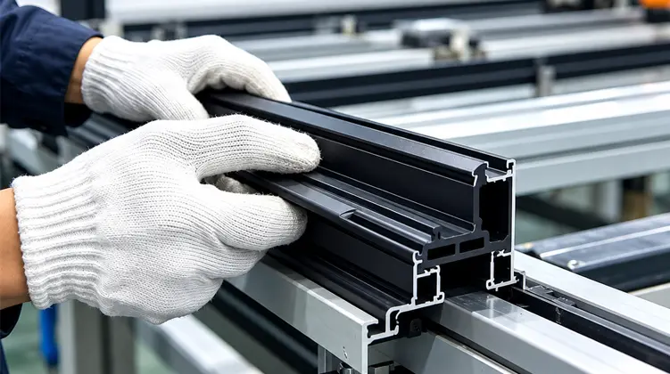
Some thermally broken aluminum systems use a rolling process to mechanically lock the polymer section into the profile. During this operation, the aluminum is formed around the inserted component and the assembly experiences mechanical loads. The polymer must retain its integrity while the locking interface is created.
Glass-fiber orientation within the extruded profile is relevant here. A well-controlled extrusion process aims to support the longitudinal strength of the section while providing the transverse shear resistance needed at the interface. The exact outcome depends on material formulation and processing conditions, so production control remains essential.
Cracking during assembly should not immediately be treated as a material-only problem. Possible contributors include an unsuitable cross-section, excessive interference, incorrect groove dimensions, unfavorable processing conditions, insufficient cooling control or assembly parameters that place concentrated stress on the profile.
Investigating the complete interface is more useful than changing one variable in isolation. The aluminum groove, polymer section and assembly process form one mechanical system.
Design perspective: mechanical stability is achieved through the interaction of material strength, section geometry and controlled assembly. A well-defined cross-section makes it easier to keep those factors aligned.
Dimensional stability starts with the raw material condition and continues through extrusion, cooling, shaping and cutting. If one stage drifts, the impact may appear later during profile assembly. This is why process parameters are more useful when recorded and monitored at the production stage rather than relying only on a final visual check.
Thermally separated aluminum systems appear in several architectural applications. The insulation component performs the same basic function across them—creating a non-metallic separation between aluminum members—but the surrounding profile geometry and mechanical loading can differ.
Window frames and sashes use separated aluminum sections to reduce the direct conductive route through the frame. The polymer section must remain stable within the groove during fabrication and use.
Door profiles need thermal separation together with mechanical stability, especially where the frame experiences repeated opening, closing and handling.
Façade framing can include mullions, transoms and other separated aluminum members. Profile geometry varies by system, so section matching is particularly important.
Special sections may be used when an extrusion has a distinctive cavity, locking interface or dimensional arrangement that does not align with a common profile.
Window assemblies usually contain multiple aluminum sections and joints, so the insulating profile needs to follow the geometry of each intended interface. The sash and frame may not use identical cavities, and a profile that works in one location may not be appropriate in another. Clear section drawings help keep the component selection aligned with each extrusion.
Doors place additional emphasis on mechanical stability because their profiles are handled frequently and may be subject to repeated movement. The insulating component has to remain engaged without becoming a source of cracking or dimensional instability during fabrication.
Curtain wall framing often involves long profile runs and multiple structural interfaces. Dimensional consistency along the extrusion becomes important because small changes repeated over a long section can influence assembly conditions. The insulation profile also needs to work with the specific mullion or transom geometry rather than an assumed generic cavity.
Architectural aluminum systems are not limited to standard geometries. A special groove, unusual section height or different locking arrangement may call for a specially developed polymer profile. In those cases, development should be guided by the aluminum extrusion and the actual assembly sequence.
Extrusion quality is influenced by the entire production chain rather than a single machine setting. Material preparation, extrusion molding, cooling, shaping and cutting each contribute to the final profile. A disciplined process makes it easier to connect finished dimensions with recorded manufacturing conditions.
PA66 nylon and glass fiber should be checked before entering the extrusion system. Material inspection can include melt flow index, glass-fiber content and moisture. These checks provide a practical baseline for process stability and help identify material variation before it becomes a dimensional problem.
Multiple parallel twin-screw extrusion lines can be combined with dedicated molds and cooling systems to produce different profile geometries. Extrusion temperature, pulling speed and cooling water temperature influence the way the material flows, exits the die and settles into its final shape.
The mold itself is an important part of the process. The tool must reproduce the intended cross-section consistently, including the small locking or guiding features that may not be obvious from a simple product name.
Immediately after extrusion, the hot profile requires controlled cooling and shaping. Cooling too quickly, too slowly or unevenly can influence dimensions and surface condition. A stable downstream process helps maintain the intended section across the production run.
Extrusion also influences the orientation of reinforcement within the polymer. The processing approach is intended to support the longitudinal strength of the profile and the transverse shear resistance at the interface. Because the strip may experience insertion and roll-forming loads, these characteristics are relevant to assembly performance.
The production target is therefore more than a visually correct cross-section. It is a section with repeatable dimensions, stable surface quality and mechanical characteristics suited to the intended assembly process.
Inspection is most useful when it is distributed across production stages. A final inspection can confirm whether the finished profile meets certain requirements, but in-process checks provide a better opportunity to identify drift before large quantities are completed.
Regular production checks can monitor cross-sectional dimensions and surface condition during the run. Process parameters can be recorded for traceability, allowing dimensional changes to be reviewed against manufacturing conditions.
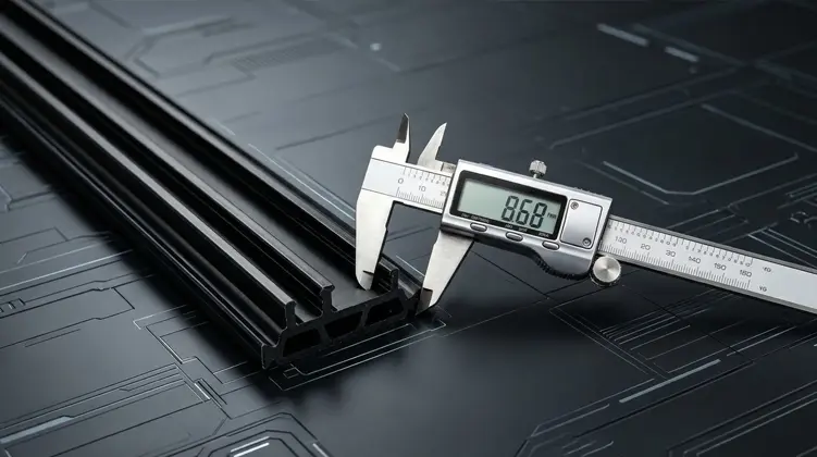
Typical visual checks focus on the profile surface, edge integrity and obvious defects. Dimensional checks focus on the width, height, wall thickness and other critical features defined by the section drawing.
Depending on the applicable requirements, laboratory evaluation can cover density, Shore hardness, longitudinal tensile strength, transverse tensile strength, water resistance, thermal aging and linear expansion characteristics. The purpose is to connect measurable material or finished-profile properties with the conditions expected in the final application.
| Inspection Area | Typical Focus | Production Value |
|---|---|---|
| Raw material | Moisture, melt flow index and glass-fiber content | Creates a stable starting condition for extrusion. |
| Profile dimensions | Width, height, wall thickness and critical geometry | Supports consistent cavity fit and locking engagement. |
| Surface condition | Visible defects, edge integrity and continuity | Helps identify extrusion or downstream shaping issues. |
| Mechanical properties | Longitudinal and transverse strength, hardness | Provides data related to assembly and service loading. |
| Environmental characteristics | Water resistance, thermal aging and linear expansion | Supports evaluation of dimensional behavior under relevant conditions. |
Before shipment, finished profiles can be checked for appearance and dimensions against the production specification. An English inspection report can accompany the goods when required, creating a clear record of the measured product condition.
Traceability is useful when a profile behaves differently during assembly. Instead of treating every issue as an isolated event, production records allow the section dimensions, process settings and inspection results to be reviewed together. This makes technical communication more precise and helps distinguish a profile-fit problem from an assembly-process problem.
Before a profile enters regular production, the most useful information is usually the information that defines the aluminum-polymer interface. A clear technical package reduces ambiguity and gives the extrusion manufacturer enough context to evaluate the appropriate section.
Terms such as I-Type, C-Type or T-Type are useful for organizing a product range, but they do not replace an engineering drawing. A profile with a similar visual shape may still have different locking dimensions or a different cavity interface. Name-based selection without geometry review increases the chance of assembly difficulties.
The extrusion profile should be evaluated alongside the assembly process. If the component is expected to pass through a rolling operation, its cross-section needs to be compatible with that load. If insertion is tight, the interference and locking geometry should be reviewed before production parameters are changed.
Useful communication focuses on measurable information: drawings, section dimensions, assembly direction, locking geometry and the intended application. Clear information allows the manufacturer to discuss an existing section or develop a special one without relying on assumptions.
Specification checkpoint: the most important question is whether the polymer profile is designed around the aluminum extrusion. When the interface is clearly defined, material, tooling and process decisions can be evaluated against the same target.
The physical supply form should match how the aluminum system is handled on the production floor. Straight sections are convenient when the production line cuts and feeds defined lengths. Coiled sections can be suitable for specifications designed for continuous handling and storage.
| Supply Form | Typical Length | Useful When | Key Consideration |
|---|---|---|---|
| Straight strip | 6 meters per piece | The extrusion line or fabrication process works with fixed straight lengths. | Confirm cutting, handling and storage requirements for the finished aluminum profile. |
| Coiled strip | 500 meters per roll for suitable specifications | Long continuous feeding and compact storage are preferred. | Check whether the selected section and assembly process are suitable for coiled handling. |
Packaging and handling should protect the profile from deformation, contamination and unnecessary mechanical stress. The appropriate method depends on the section shape and the way the material moves from storage to the aluminum assembly process.
For some profile geometries, a coiled form may introduce handling requirements that do not apply to straight lengths. Those requirements should be considered alongside the actual fabrication equipment rather than selected independently from the profile design.
Technical problems are often easier to resolve when the symptom is separated from its possible causes. The same visible issue can come from more than one stage of the process, so troubleshooting should follow the path from aluminum geometry to polymer section to assembly conditions.
| Observed Issue | Possible Area to Review | Useful Check |
|---|---|---|
| Difficult insertion | Section width, locking feature or aluminum cavity | Compare actual dimensions with the approved drawing and review insertion conditions. |
| Cracking during assembly | Interference, material condition, geometry or process load | Inspect the section, material processing records and assembly sequence together. |
| Insufficient shear resistance | Material reinforcement, cross-section or locking interface | Review applicable mechanical test data and check the engagement geometry. |
| Variable profile dimensions | Extrusion temperature, pulling speed or cooling | Compare in-process measurements with recorded production parameters. |
| Loose engagement | Groove dimensions, locking shape or undersized section | Confirm cavity geometry and compare actual profile dimensions with the target section. |
When insertion feels unusually difficult, increasing force is not always the right answer. The first step is to check whether the polymer width and locking features match the aluminum cavity. Misalignment, dimensional variation or a mismatch between the intended and actual groove geometry can all increase assembly resistance.
Cracking may result from concentrated stress during insertion or rolling. It can also be associated with material condition or extrusion stability. A controlled diagnosis compares the affected section with production measurements and the aluminum interface instead of changing the material grade without evidence.
Shear performance is related to both material reinforcement and interface geometry. If the locking area is too small or poorly matched, a mechanically strong polymer may still fail to achieve the required engagement. Testing and dimensional review should therefore be considered together.
This approach helps turn assembly issues into specific engineering questions. That is especially useful during profile development, where an adjustment to one dimension may influence several parts of the interface.
Thermal Break Strips separate interior and exterior aluminum sections and reduce direct heat transfer through thermally broken aluminum profiles. The polyamide section creates a non-metallic barrier inside the frame while also serving as a mechanical interface for the assembled aluminum sections.
The core material is PA66 nylon reinforced with 25% glass fiber, commonly described as PA66 GF25. The reinforcement provides the rigidity and mechanical stability required for insertion, rolling and continued engagement within aluminum profiles.
The range includes I-Type, C-Type, T-Type and special-shaped sections for aluminum windows, doors, curtain walls and other thermally separated architectural extrusion systems.
Common applications include aluminum window frames and sashes, aluminum doors, curtain wall mullions and transoms, and other architectural aluminum sections that require thermal separation between interior and exterior members.
Yes. Customized dimensions and cross-sections can be developed around the actual aluminum extrusion geometry. A profile drawing with the cavity dimensions and locking structure provides a practical basis for section selection and tooling review.
An aluminum profile drawing, required section dimensions, locking geometry, insertion direction, assembly method and important tolerances are useful starting points. The clearer these details are, the easier it is to confirm whether a standard section or a special profile is appropriate.
Straight strips are supplied at 6 meters per piece. Coiled strips are available at 500 meters per roll for suitable specifications. The most appropriate form depends on the section geometry and the handling method used in production.
Yes. Technical assistance can cover profile slot design, strip insertion, roll-forming conditions and common production problems such as difficult insertion, cracking and insufficient shear resistance.
Finished profiles are inspected for appearance and dimensions before shipment. Depending on the applicable requirements, laboratory evaluation can also cover density, Shore hardness, longitudinal and transverse tensile strength, water resistance, thermal aging and linear expansion characteristics.
Thermal separation works best when the polymer component is treated as part of the aluminum system rather than as an interchangeable accessory. The material provides the non-metallic barrier, reinforcement provides mechanical support, and the cross-section determines how the component engages with the extrusion. Production control then keeps that intended geometry consistent from raw material through finished profile.
For established systems, a suitable I-Type, C-Type or T-Type section may already meet the required interface. For a new or unusual extrusion, a customized geometry can be evaluated from the drawing, cavity dimensions and assembly method. This profile-based approach keeps the technical discussion focused on dimensions, mechanical engagement and practical production conditions.
For architectural aluminum manufacturers, a clear specification should connect four elements: the aluminum extrusion, the polyamide section, the production process and the applicable quality requirements. When these elements are considered together, the resulting profile is easier to manufacture, assemble and inspect consistently.
Share the section drawing, cavity dimensions and assembly requirements to discuss a suitable standard or customized PA66 GF25 profile for your thermally separated aluminum system.
Contact us to discuss your aluminum profile requirements