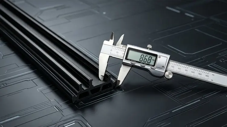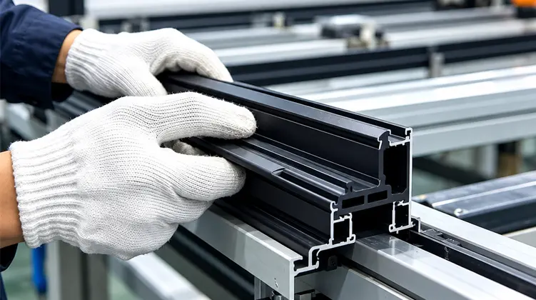

The performance of a thermally broken aluminum frame depends on more than choosing a polyamide material. Profile geometry, reinforcement, dimensional control, assembly compatibility, and application conditions all influence whether the insulation section remains secure and functional throughout production and service.
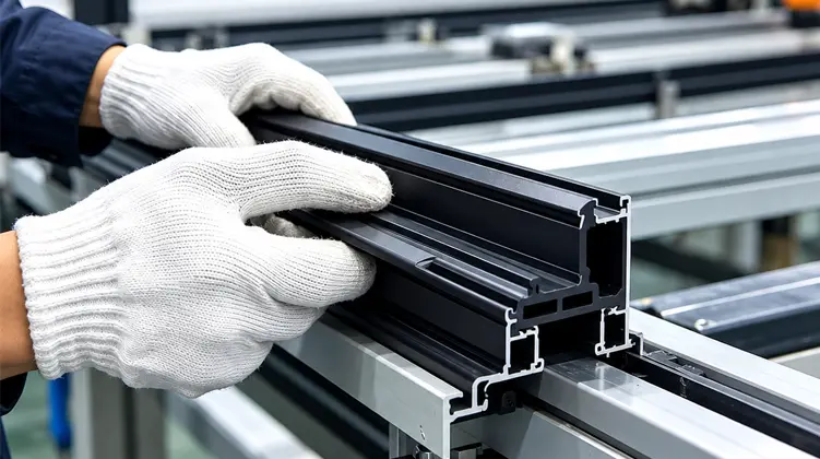
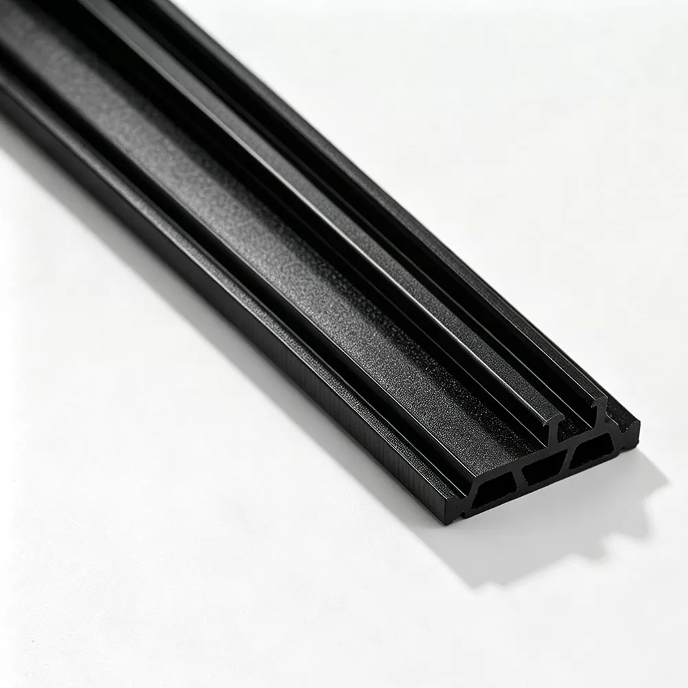
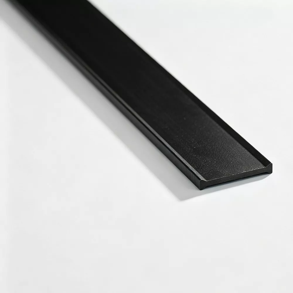
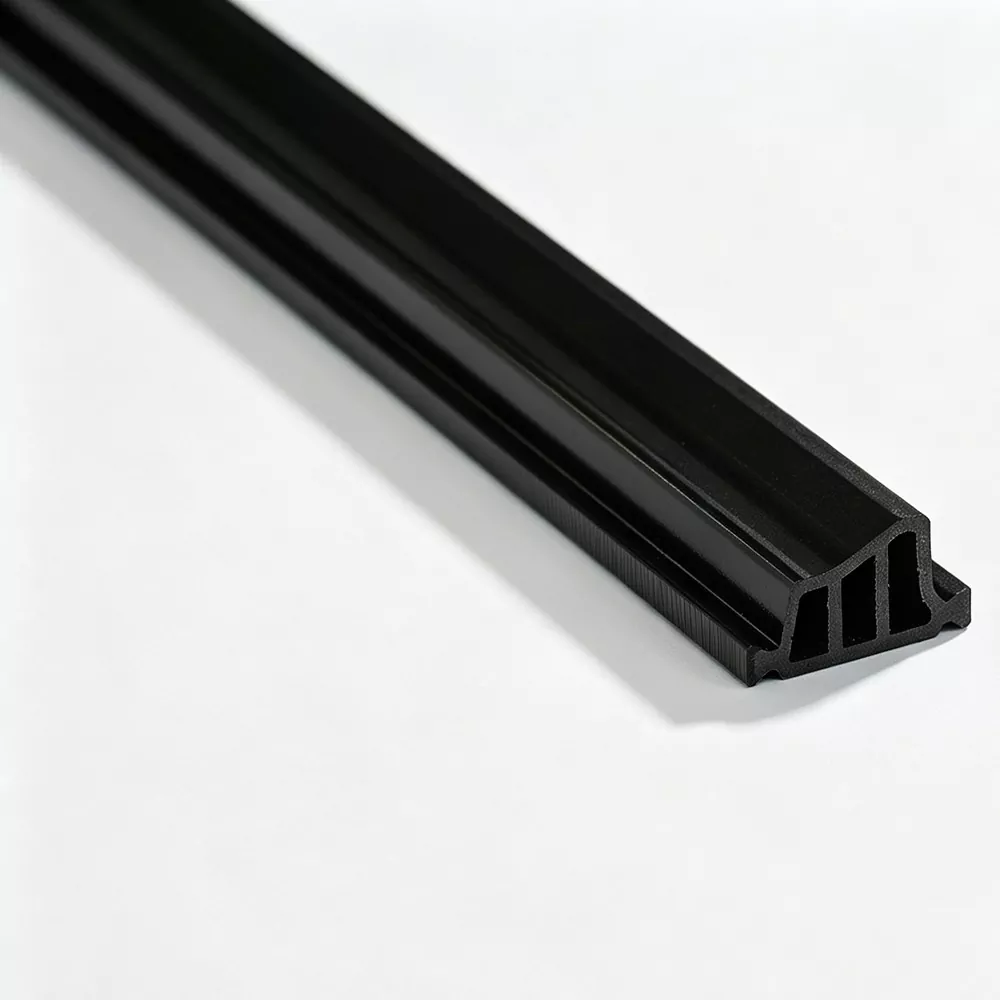
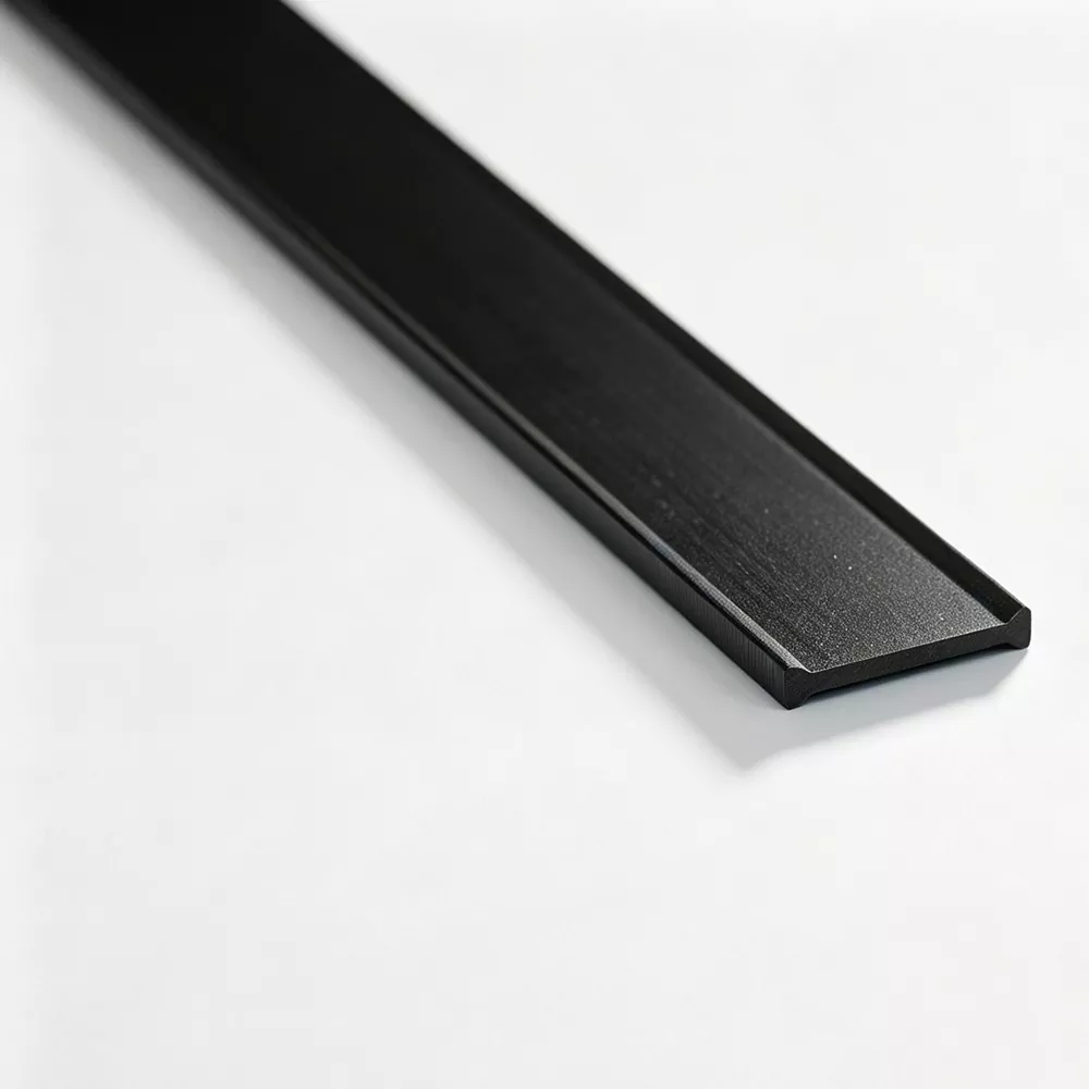
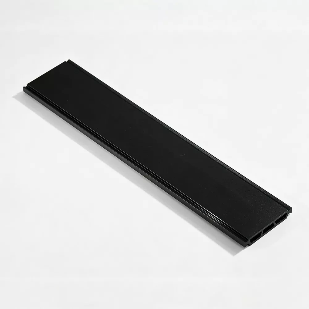
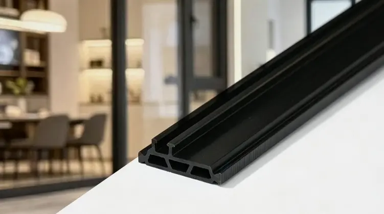
PA66 GF25 Thermal Break Strips are reinforced polyamide insulation profiles used to separate interior and exterior aluminum sections and interrupt the direct metal heat-transfer path through thermally broken frames. A suitable strip must match the aluminum extrusion rather than being selected by material name alone. Width, height, thickness, groove geometry, locking structure, required separation, and the assembly process all need to be considered together. The material is commonly reinforced with 25% glass fiber to improve rigidity and mechanical stability. For architectural systems, the practical objective is a profile that can be inserted or roll-formed consistently, retain its dimensions, and remain mechanically engaged with the surrounding aluminum sections.
Table of Contents
Click a section below to jump directly to it.
- Why the Thermal Break Section Matters
- What PA66 GF25 Means in Practice
- How Aluminum Profile Geometry Determines the Strip
- Which Profile Types Are Commonly Used?
- Where These Insulation Profiles Are Applied
- How the Extrusion Process Affects Profile Quality
- What Should Be Checked During Quality Control?
- What Should Assemblers Watch For?
- How to Prepare for a New Profile Development
- Frequently Asked Questions
Why the Thermal Break Section Matters
Aluminum is valued for its strength, corrosion resistance, appearance, and ease of extrusion, but aluminum also conducts heat readily. A thermally broken design addresses that characteristic by separating the aluminum sections with a non-metallic material.
In a thermally separated window, door, or curtain wall assembly, the interior aluminum section and exterior aluminum section are not intended to form one uninterrupted metallic path. Instead, a polyamide profile is positioned between them. This creates a physical interruption in the conductive route and supports the thermal separation strategy of the frame.
The strip therefore has two jobs that must work together. First, it needs to create the intended separation between the aluminum parts. Second, it has to remain mechanically engaged with the profile during assembly and later use. A strip that provides separation but does not fit the cavity correctly is not a practical solution. Likewise, a strip that fits dimensionally but lacks the mechanical stability required for insertion and rolling can create production problems.
Thermal Function
The polyamide section interrupts direct metal-to-metal heat transfer through the frame and supports the overall thermal-break concept of the aluminum extrusion.
Mechanical Function
The profile must stay engaged with the aluminum sections and resist the mechanical demands introduced during insertion, rolling, shaping, and service.
This is why strip selection should begin with the aluminum profile rather than with a catalog name. The cavity, groove, locking structure, and required depth of engagement provide the actual engineering constraints.
What PA66 GF25 Means in Practice
PA66 refers to polyamide 66, an engineering thermoplastic known for its combination of strength, stiffness, dimensional stability, and resistance to mechanical loading. The “GF25” designation indicates that the material contains 25% glass fiber reinforcement. In a thermal break profile, this reinforcement is used to raise rigidity and improve mechanical stability compared with an unreinforced polyamide formulation.
25% Glass-Fiber Reinforcement
A reinforced polyamide profile needs to cope with forces generated during assembly. In many thermally broken aluminum systems, the strip is inserted into prepared grooves and then secured through a rolling process. The reinforcement helps the profile maintain a stable shape when mechanical force is applied along the assembly path.
Glass fiber also affects the behavior of the material in ways that make process control important. Fiber distribution and orientation can influence longitudinal strength, transverse shear resistance, surface appearance, and dimensional consistency. A production process therefore has to control more than extrusion temperature alone.
Dimensional Stability
A thermal break strip is a precision profile rather than a simple sheet of plastic. Its width, height, wall geometry, locking features, and thickness need to remain consistent enough to match the aluminum cavity. Small dimensional changes can influence insertion force, engagement depth, and the final mechanical connection.
Extrusion, cooling, and shaping conditions all contribute to that stability. Cooling that is too aggressive or poorly balanced can affect shrinkage and profile shape. Pulling speed also influences the dimensions of a continuous extruded section. For this reason, profile production requires coordinated control of heat, speed, tooling, and cooling conditions.
Resistance to Long-Term Mechanical Demand
Thermal break profiles can remain inside an aluminum frame for many years. During that period, the material is expected to maintain sufficient mechanical integrity while exposed to repeated environmental changes. The exact requirements depend on the frame system, local climate, design standard, and intended service conditions.
- Stiffness: important for maintaining the section shape during profile assembly.
- Dimensional consistency: necessary for predictable engagement with the aluminum extrusion.
- Shear resistance: relevant where the strip is subjected to forces generated by assembly and profile loading.
- Thermal stability: relevant because the frame experiences temperature changes during service.
- Process consistency: essential when the same strip geometry is used across repeated production runs.
These characteristics explain why a reinforced engineering polymer is used in place of a generic plastic profile. The thermal break section has to function as part of a structural assembly, not merely as an insulating spacer.
How Aluminum Profile Geometry Determines the Strip
A successful thermal break design starts with the actual aluminum extrusion. Product names such as I-Type, C-Type, or T-Type describe general section families, but they do not replace the dimensional information required for a correct match.
The most useful engineering approach is to compare the aluminum cavity with the corresponding dimensions of the polyamide strip. The relationship can be summarized through the following factors.
| Aluminum Profile Factor | Related Strip Requirement | Why the Match Matters |
|---|---|---|
| Cavity width | Strip width | The strip needs to occupy the intended cavity without excessive looseness or excessive insertion resistance. |
| Cavity depth | Profile height | The height influences how deeply the strip engages with the aluminum section. |
| Groove structure | Locking geometry | The locking features must interact correctly with the prepared aluminum grooves. |
| Required separation | Strip thickness | The thickness contributes to the intended separation between the aluminum sections. |
| Assembly process | Insertion and rolling compatibility | The section has to tolerate the selected production method without cracking or losing dimensional control. |
Start With a Drawing or Physical Profile
A dimensioned aluminum extrusion drawing provides the clearest starting point because it shows the cavity width, groove dimensions, wall geometry, and critical tolerances. A physical profile can also provide useful information when the drawing is unavailable or when the actual extrusion needs to be verified.
For development work, the most useful information generally includes:
- The aluminum cavity width and depth.
- The location and shape of the locking grooves.
- The required thermal separation between the aluminum sections.
- The intended strip cross-section and dimensional tolerances.
- The assembly sequence used to insert and secure the profile.
- Any known production issue, such as difficult insertion or cracking.
Why Section Accuracy Matters
Imagine a strip that is slightly too wide for the extrusion cavity. The insertion force may increase, and the installer or production line may need more mechanical pressure than intended. A strip that is too narrow can create the opposite problem: insufficient engagement or movement during assembly.
Height and locking geometry matter in a similar way. A profile can look correct in isolation while still failing to engage with the specific aluminum groove. That is why thermal break development is best treated as a matched profile system.
Review the available polyamide section range together with the aluminum profile dimensions before finalizing a specification.
Which Profile Types Are Commonly Used?
Different aluminum extrusion geometries call for different thermal break sections. The profile family is usually identified by its cross-sectional shape and locking arrangement.
I-Type Profiles
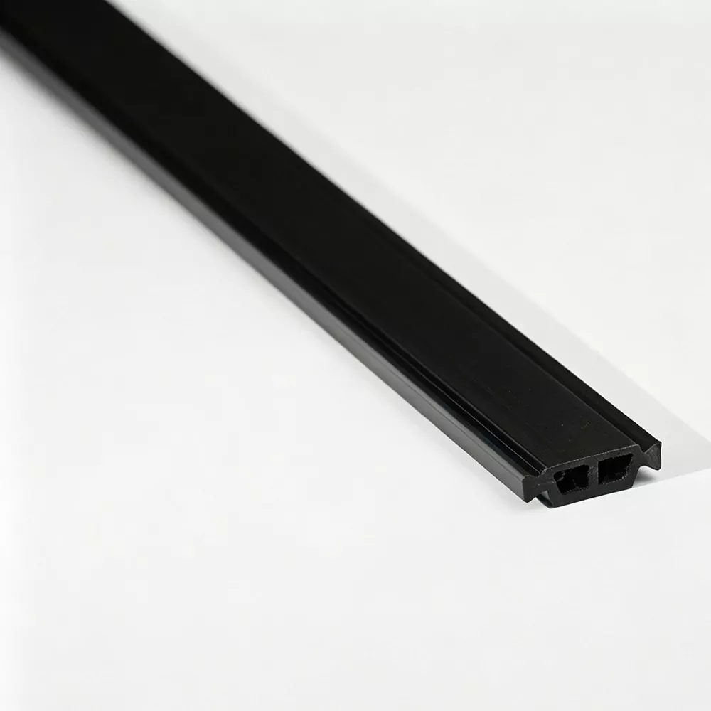
I-Type sections are commonly associated with a relatively straightforward thermal separation geometry. Their final suitability depends on the width, height, groove arrangement, and engagement conditions of the aluminum extrusion. The “I” designation should therefore be treated as a profile family rather than a universal dimension.
C-Type Profiles
C-Type sections are shaped around a different engagement geometry and may be selected where the aluminum extrusion uses a corresponding cavity or locking structure. The opening and side features need to be matched carefully to the aluminum profile.
T-Type Profiles
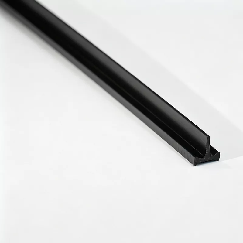
T-Type sections are used where the aluminum extrusion contains geometry suited to a T-shaped engagement profile. The exact dimensions, shoulder positions, and locking details determine whether the strip can be inserted and secured correctly.
Special-Shaped Sections
Some aluminum systems use grooves or cavities that do not align with standard section families. In those cases, a special cross-section can be developed around the actual extrusion. The most important input is the aluminum profile drawing or physical sample of the profile itself, together with the assembly method and critical dimensions.
Where These Insulation Profiles Are Applied
Thermally broken aluminum systems are used across several architectural applications. Although the design objective is related in each case, the profile geometry and mechanical requirements can vary according to the frame structure.
Aluminum Windows
Thermal break profiles are installed between interior and exterior aluminum sections of window frames and sashes. The strip supports thermal separation while remaining mechanically engaged within the frame construction.
Aluminum Doors
Door profiles require a stable connection because the finished assembly may experience repeated opening, closing, handling, and environmental exposure. The thermal break section has to remain compatible with the selected locking and rolling process.
Curtain Wall Systems
Curtain wall framing can include mullions, transoms, and related thermally separated aluminum sections. Profile dimensions can differ substantially between systems, so geometry matching remains essential.
Other Architectural Aluminum Profiles
Special thermally separated extrusions can also require non-standard insulation sections. Custom profile development can address unusual dimensions, groove structures, or assembly constraints.
Application conditions should also be considered when selecting the material formulation and profile geometry. A frame installed in a temperature-variable environment may experience repeated dimensional movement, while a façade system can introduce additional mechanical and environmental demands.
It is important to distinguish the thermal function of the strip from the total thermal performance of the finished frame. The strip interrupts direct conduction through the aluminum section, but the final thermal behavior of a window, door, or curtain wall also depends on glass, seals, frame geometry, air chambers, joints, and installation details.
How the Extrusion Process Affects Profile Quality
The consistency of a thermal break profile depends heavily on how the reinforced polyamide compound is processed. A controlled production sequence helps keep the cross-section stable from raw material through finished length.
Material Blending
PA66 resin and glass fiber are prepared and controlled before entering the extrusion process.
Extrusion Molding
The reinforced material passes through profile tooling to create the required cross-sectional geometry.
Cooling and Shaping
Cooling conditions and pulling speed are controlled to stabilize dimensions after extrusion.
Precision Cutting
The continuous profile is cut or prepared in the requested supply form for subsequent use.
Raw Material Control
The starting material has a direct influence on extrusion behavior. Incoming PA66 and glass-fiber materials can be checked for characteristics such as melt flow index, reinforcement content, and moisture condition. Moisture management is particularly relevant for polyamide processing because water content can affect melt behavior and final material performance.
Extrusion Temperature and Pulling Speed
Reinforced polyamide must be processed within controlled temperature conditions so that the melt fills the profile die consistently without creating unnecessary degradation or dimensional instability. Pulling speed also influences profile size because the extrudate can change dimension as it cools.
For this reason, temperature and line speed should be considered as a coordinated process rather than as isolated settings. When a profile contains narrow grooves or small locking features, even modest changes in dimensional behavior can influence the final fit.
Cooling and Shaping
Cooling is one of the most important stages for profile stability. The cooling system needs to remove heat in a controlled way so that the extruded section maintains its intended geometry. Uneven cooling can contribute to distortion, warping, or inconsistent dimensions across the profile.
Glass-Fiber Orientation
The extrusion process also influences glass-fiber orientation. Controlled orientation can support longitudinal strength while maintaining the mechanical characteristics needed across the section. This becomes particularly relevant for profiles that need to tolerate insertion and roll-forming forces.
The production system described for Jinxing includes material preparation, multiple parallel twin-screw extrusion lines, self-developed molds, cooling systems, shaping, and cutting. The process is arranged so that the principal manufacturing stages remain within one production system.
What Should Be Checked During Quality Control?
Quality control for thermal break profiles is more useful when it covers the production process as well as the finished product. Final inspection can identify defects, but regular in-process checks provide earlier information about dimensional drift or surface problems.
In-Process Inspection
During continuous extrusion, production samples can be checked at regular intervals for cross-sectional dimensions and visible defects. Process parameters can also be recorded so that changes in the production line can be connected with later dimensional results.
- Cross-sectional width and height.
- Critical groove and locking dimensions.
- Wall thickness and profile symmetry where relevant.
- Surface defects, deformation, or visible cracking.
- Production parameter records for traceability.
Laboratory Evaluation
Depending on the applicable requirements, additional laboratory evaluation may cover density, Shore hardness, longitudinal tensile strength, transverse tensile strength, water resistance, thermal aging, and linear expansion characteristics.
These tests do not all answer the same engineering question. Tensile strength provides information about resistance to pulling forces, while transverse strength is more relevant to stresses acting across the profile. Linear expansion helps engineers understand dimensional movement associated with temperature changes.
Pre-Shipment Inspection
Before shipment, finished strips can be inspected for appearance and dimensions. Straight profiles may be prepared in lengths such as 6 meters per piece, while suitable specifications can also be supplied in coils such as 500 meters per roll. The practical supply form depends on profile geometry and downstream assembly requirements.
An English inspection report can accompany the goods where required. Clear inspection information can help production teams verify that the received profile corresponds with the agreed specification.
| Inspection Stage | Main Focus | Production Purpose |
|---|---|---|
| Incoming material check | Material condition and reinforcement characteristics | Confirm that the starting compound is suitable for controlled extrusion. |
| In-process inspection | Dimensions and surface condition | Detect profile drift before a long production run is completed. |
| Laboratory testing | Mechanical, thermal, and physical characteristics | Evaluate properties against applicable technical requirements. |
| Pre-shipment inspection | Appearance, dimensions, and order consistency | Verify the finished profile before dispatch. |
What Should Assemblers Watch For?
Even a precisely extruded strip can create problems when the aluminum profile, tooling, and assembly conditions are not matched correctly. Insertion and rolling should therefore be treated as part of the profile design rather than as separate downstream concerns.
Insertion Force
A strip that enters the aluminum groove with excessive resistance may indicate dimensional mismatch, an unsuitable locking geometry, or an assembly condition that needs adjustment. High insertion force can increase the risk of profile damage, especially where the section contains narrow walls or sharp locking features.
Cracking During Assembly
Cracking should not automatically be attributed to the material itself. Possible causes can include excessive mechanical force, unsuitable groove geometry, overly tight dimensions, poor alignment, or incorrect processing conditions. Reviewing the aluminum extrusion and the assembly sequence together is often more productive than examining the strip in isolation.
Insufficient Shear Strength
The final connection needs to withstand the loads expected from handling and service. If the engaged strip does not provide sufficient resistance to relative movement between the aluminum sections, the issue may involve profile geometry, material characteristics, or the rolling process.
Consistency Across the Production Line
A profile that works well during a single trial run should also behave consistently during repeated production. Consistent strip dimensions make it easier to maintain stable insertion and rolling conditions across multiple batches of aluminum extrusion.
- Check the aluminum groove: confirm that the cavity is clean, dimensionally correct, and compatible with the strip.
- Check insertion alignment: misalignment can increase force and damage the profile edge.
- Check rolling conditions: confirm that the mechanical process is appropriate for the strip geometry.
- Track dimensional consistency: compare incoming and in-process profile measurements when unexpected assembly behavior appears.
These checks are particularly useful when moving from a prototype extrusion to repeat production, because a small dimensional difference can become much more noticeable when many profile lengths are processed continuously.
How to Prepare for a New Profile Development
Developing a thermal break section for a new aluminum extrusion is easier when the information is organized before tooling is considered. The objective is to define the complete interface between the polyamide section and the aluminum profile.
A practical development sequence can follow several stages:
- Review the aluminum drawing: identify cavity dimensions, groove geometry, wall thickness, and critical tolerances.
- Confirm the thermal separation requirement: determine the intended distance between the interior and exterior aluminum sections.
- Define the strip cross-section: establish width, height, thickness, locking details, and any special features.
- Review the assembly process: confirm insertion direction, rolling method, and expected mechanical force.
- Evaluate production behavior: check dimensional stability, surface quality, and assembly performance.
- Finalize the production specification: document the agreed profile geometry, material construction, inspection points, and supply form.
Use the Aluminum Profile as the Main Reference
The most common mistake in profile development is starting with a generic strip dimension and trying to force the aluminum extrusion to match it. The more reliable approach is the reverse: start from the extrusion and define the insulation section around the actual interface.
A physical aluminum profile can be especially useful when the extrusion drawing does not fully represent manufacturing variation. Comparing the drawing with the real section helps identify practical issues such as groove depth, edge radius, or local dimensional differences.
Keep Thermal and Mechanical Requirements Together
The strip should not be designed for thermal separation while its mechanical engagement is treated as an afterthought. The two functions are connected. A thicker section may alter the cavity relationship. A different locking shape can change insertion force. A tighter fit may affect assembly behavior. Engineering decisions should therefore consider the complete cross-section.
Plan for Repeatability
A good section should not only work once. It should be capable of being extruded consistently, cut or coiled in a controlled manner, transported without unnecessary deformation, and assembled repeatedly with predictable behavior.
Understanding the Term in Product Searches
When engineers or procurement teams search for PA66 GF25 Thermal Break Strips, the search term often represents a technical requirement rather than a single universal product. The “PA66” portion identifies the polyamide family, while “GF25” indicates the 25% glass-fiber reinforcement. The remaining specification still depends on the aluminum extrusion and the intended assembly process.
For that reason, product evaluation should move from the keyword level to the engineering level. A technically appropriate strip is defined by the combination of material, section dimensions, locking geometry, production consistency, and compatibility with the target aluminum profile.
Frequently Asked Questions
What are Thermal Break Strips used for?
They are used to separate interior and exterior aluminum sections and reduce direct heat transfer through thermally broken aluminum profiles. The strip also provides a mechanical connection within the aluminum extrusion when the geometry and assembly process are correctly matched.
What material are these thermal break profiles made from?
The core material is PA66 nylon reinforced with 25% glass fiber. This reinforced construction is commonly identified as PA66 GF25 and is selected for the stiffness, dimensional stability, and mechanical characteristics required by thermally broken aluminum systems.
What profile types are commonly available?
Common section families include I-Type, C-Type, and T-Type profiles. Special-shaped sections can also be developed for aluminum extrusions with unusual cavity dimensions or locking geometries.
Where are thermal break profiles commonly used?
Typical applications include aluminum windows, aluminum doors, curtain wall systems, mullions, transoms, and other architectural aluminum profiles that require thermal separation between interior and exterior sections.
Can the cross-section be customized?
Yes. A customized section can be developed around an aluminum profile drawing or physical profile, with attention to strip width, height, thickness, groove structure, locking geometry, and the intended assembly method.
What information is useful for a customized thermal break strip?
Useful information includes the aluminum profile drawing or physical profile, required strip dimensions, locking structure, target thermal separation, and the insertion or roll-forming method used during assembly.
What supply forms can be used?
Suitable specifications can be supplied as straight strips, including 6-meter lengths per piece, or as coiled profiles such as 500 meters per roll. The practical form depends on the profile geometry and the downstream production process.
What quality characteristics should be evaluated?
Evaluation can include profile dimensions, appearance, density, Shore hardness, longitudinal and transverse tensile strength, water resistance, thermal aging, and linear expansion characteristics, according to the requirements applicable to the intended system.
Can technical assistance cover assembly problems?
Technical support can address profile slot design, strip insertion, roll-forming conditions, and common issues such as difficult insertion, cracking, or insufficient shear strength. Reviewing the aluminum extrusion and assembly process together can help identify the underlying cause.
How should engineers compare different thermal break strip options?
Compare the material construction, profile dimensions, locking geometry, dimensional consistency, assembly compatibility, inspection approach, and supply form. The most meaningful comparison is based on how well the strip matches the actual aluminum extrusion rather than on the product name alone.
A Practical Specification Checklist
Before finalizing a thermal break profile, it helps to confirm the major technical variables in one place. The checklist below can be used during profile review, supplier communication, tooling preparation, or production approval.
- Confirm the PA66 material construction and 25% glass-fiber reinforcement requirement.
- Measure the aluminum cavity width and depth.
- Verify the groove shape and locking geometry.
- Define the required strip thickness and separation dimension.
- Check the strip cross-section against the real aluminum profile.
- Review insertion and roll-forming conditions before production approval.
- Confirm dimensional inspection points and acceptable tolerances.
- Check the required straight or coiled supply form.
- Document the agreed profile drawing and critical technical features.
- Keep production and inspection records available for traceability.
This checklist does not replace the engineering requirements of a specific window, door, or façade system. It provides a practical framework for making sure the material and profile interface has been defined before production begins.
The central idea remains simple: thermal break performance starts with effective separation, but dependable system performance requires a properly matched cross-section, controlled extrusion, stable dimensions, and a compatible assembly process.
Need to Match a Strip to Your Aluminum Extrusion?
Share the aluminum profile drawing, physical profile details, required dimensions, and assembly method so the appropriate section geometry can be reviewed for your thermally broken aluminum system.
contact us to discuss your profile requirements